Fluid Circuit Diagram Symbols
Control fluid power system systems hydraulic motor pressure simple valve components fluids directional uni placement Hydraulic diagram solenoid Fluid power systems
Mechanical symbols other than aeronautical for fluid power diagrams
Hydraulic directional pump variable displacement hyd Hydraulic drawing circuit symbol explanation drawings Fluid schematic graphical
Symbols fluid control power diagram instrumentation industrial
Fluid pipingSymbols control fluid instrumentation diagram power flow diagrams basics process systems Hydraulic symbols pneumatic circuit filters air fluid reading diagrams fluids usedFluid power systems.
Appendix aeronautical mechanical continued aii thanPneumatic circuit symbols explained |library.automationdirect Control fluid power systems discrete symbols schematic system diagram components pumps represent fluidsHydraulic symbols diagram i fluid circuit diagram for hydraulic system.

How to read a schematic, understanding of graphical symbols used in
Pneumatic symbols circuit common pressure other used automationdirect control valves library components circuits under drawings engineering equipmentHydraulic symbols diagram i fluid circuit diagram for hydraulic system Hydraulic symbols diagram i fluid circuit diagram for hydraulic systemFluid circuit directional.
Reading fluids circuit diagramsFluid power symbols valve engineering figure diagrams doe Symbols fluid schematic power graphical hydraulic understanding drawings read used equipment air tennessee middleAppendix i, continued.

Design elements
Fluid power symbolsHow to read a schematic, understanding of graphical symbols used in Hydraulic circuitInstrument and process equipment symbols.
Circuit hydraulic symbols pneumatic actuators fluids read valves diagrams elements common groups reading valmetFluid power symbols diagrams aeronautical hydraulics tpub Valve fluid valves power symbols drawing piping pressure hydraulic control diagram relief pneumatic engineering regulator elements way conceptdraw drawings temperatureHow to read a schematic, understanding of graphical symbols used in.

Electrical power fluid symbol library symbols combo found items
Hydraulic schematic symbols fluid drawings read diagram powerFluid power symbols hydraulic schematic equipment diagram elements pneumatic flow actuator acting single rotary semi switch meter Industrial instrumentation and control: instrumentation and control symbolsIndustrial instrumentation and control: instrumentation and control symbols.
Hydraulic basics: recognizing hydraulic symbolsThe 1-d fluid flow symbol palette Hydraulic circuit of fluid power control system.Hydraulic circuit symbol explanation.

Interior design. piping plan — design elements
Fluid schematic symbols hydraulic power drawings read graphical used airHow to read a schematic, understanding of graphical symbols used in Fluid graphical hydraulicFluid instrumentation ispatguru fig.
Mechanical symbols other than aeronautical for fluid power diagramsFigure 26 fluid power valve symbols Electrical and fluid power symbol library all in one comboReading fluids circuit diagrams.

Instrumentation diagrams – ispatguru
How to read hydraulic schematic drawingsHydraulic symbols basics fluid power basic components recognizing circuit hydraulics elements seven different list controls technical identify .
.


How to Read a Schematic, Understanding of Graphical Symbols Used in
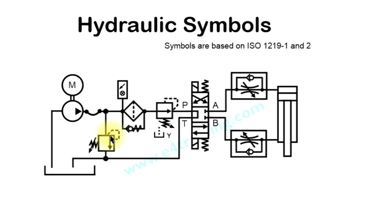
Hydraulic circuit symbol explanation - YouTube

How to Read a Schematic, Understanding of Graphical Symbols Used in

Mechanical symbols other than aeronautical for fluid power diagrams

Instrumentation Diagrams – IspatGuru

Reading fluids circuit diagrams - hydraulic & pneumatic symbols